Blue
A hand-wired Bluetooth keyboard, created in late 2018.
I somehow don’t have a photo of the complete board on me. Whoops. At some point, there will be a shiny picture of the keyboard here…
I got myself an iPad Pro back in July 2018, and realized that because of Apple’s curious dislike of any and all ports, I couldn’t connect any of my keyboards to it unless they were Bluetooth, and I had no Bluetooth keyboards.
I thought that this was a big enough problem for me to design, build, and handwire my own Bluetooth keyboard. After having exactly 0 experience in both Bluetooth-y things and also handwiring.
Somehow, the contraption worked, despite some glaring design inefficiencies. Nevertheless, I hope the process might be interesting and / or useful in some way.
Prologue
I decided early on that this board needed to meet the following criteria:
- Bluetooth-powered (duh).
- QMK-powered
As a result, I made the decision very quickly to use the Adafruit Feather BLE Atmega32u microcontroller to power the board, because it was the only microcontroller that I could find that was supported by QMK and had some existing documentation.
I decided to hand-wire the board primarily because I couldn’t find any PCBs that would support a BLE feather, and with that, I decided also to make my own layout and pretty much make the whole board from scratch.
List of Materials
- 49 Outemu Sky switches
- 49 Amoeba PCBs (I used them to reduce wire clutter; they aren’t really needed on most handwire builds)
- 49 1N4148 diodes
- 1 Adafruit Feather BLE Atmega32u
- 1 Lithium Ion Battery
- 1 Toggle switch
- 24x12 Aluminum Sheet
- 16 M2 Screws
- 8 M2 Standoffs (14mm)
- 3 Plate-mounted stabilizers (2u)
Designing the Layout
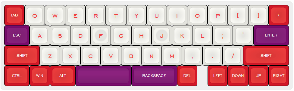
I used Keyboard Layout Editor. The layout was modified off of the Ddnano’s layout; I wanted a 40% profile (so no number row), but a full-sized home row with quotes, semicolon, and enter key. Having full-width rows also let me add the bracket and pipe keys, which are very handy as a programmer.
I was trying something new with the arrows on the bottom. I do use arrow keys quite often, but a board this size wouldn’t have room for a proper cluster without moving the right shift (which is the shift I hit regularly), so I put them all in a row at the bottom. To this date I haven’t quite gotten used to them, but it was better than not having them at all.
Anyway, I sort of winged the layout, decided it was worth building, and made some plates for it.
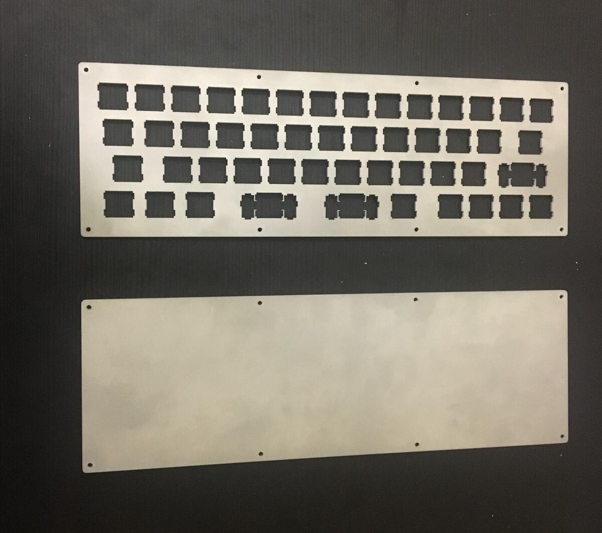
Creating Plates
- Using plate builder tool
- Sandwich case
- 2.1mm diameter for screw holes - good for M2 size
- 2mm bevel
- 6mm padding or something. I eyeballed it.
Plates were cut with a waterjet cutter, and then sandblasted.
Stabilizers
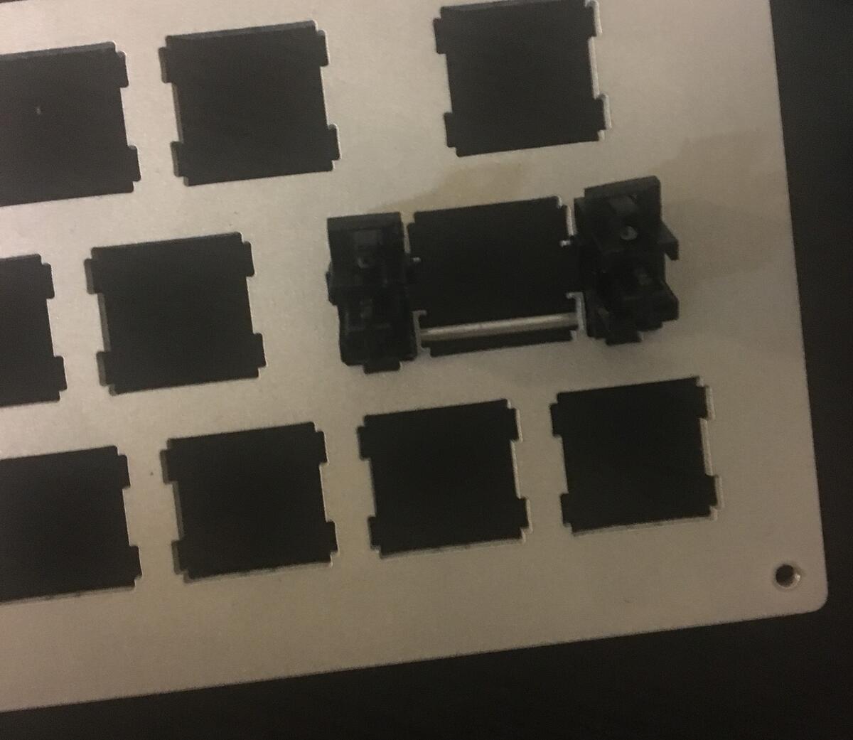
Installing the stabilizer involves sliding the bar underneath the plate (towards the bottom of the plate here, because of the cutouts) and then snapping the stabilizer into place.
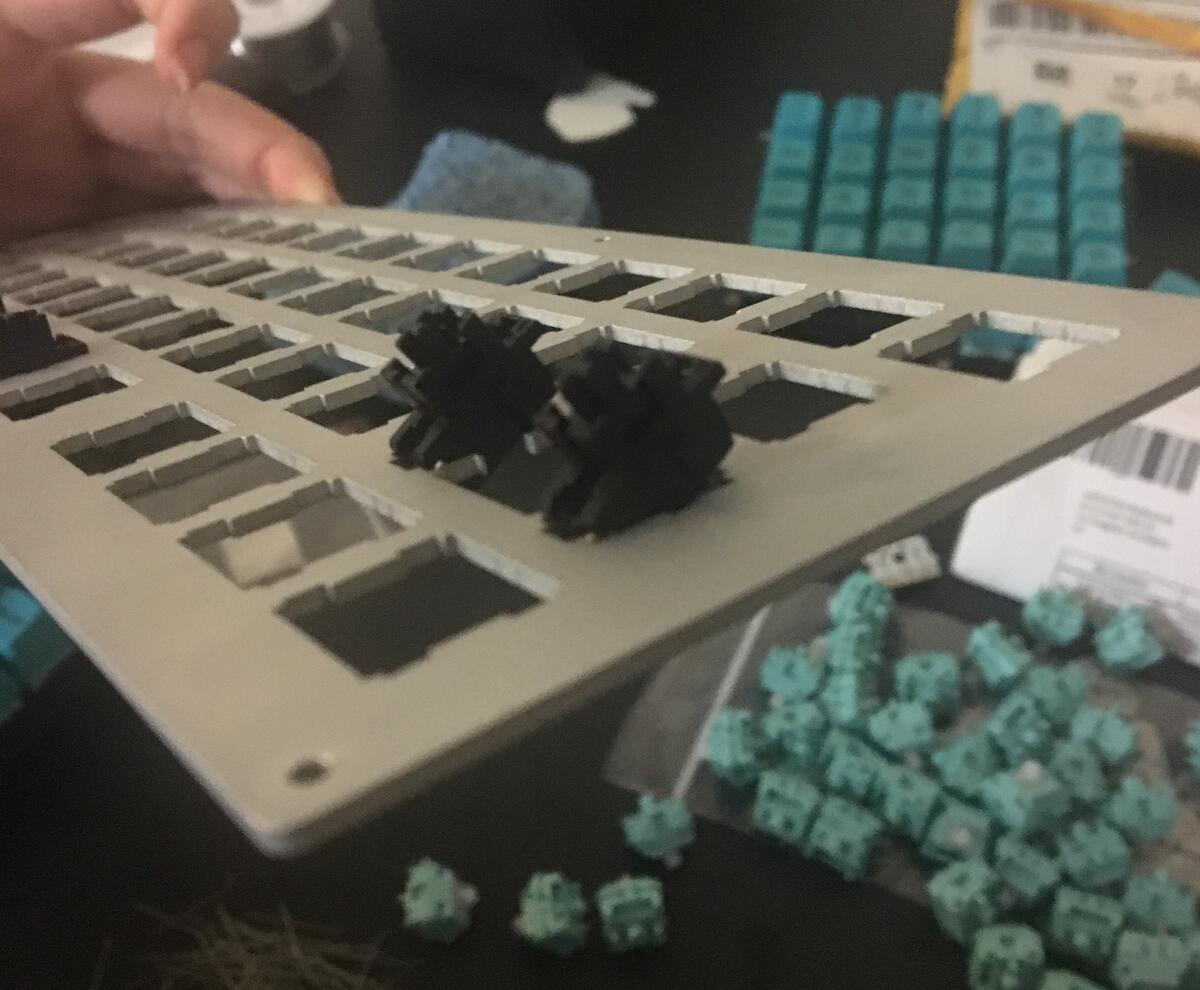
Unfortunately, I didn’t have any lube to mod them, and they feel a little mushy. I could probably fix that by desoldering a switch to take out each stabilizer, but that’s for my future self to deal with.
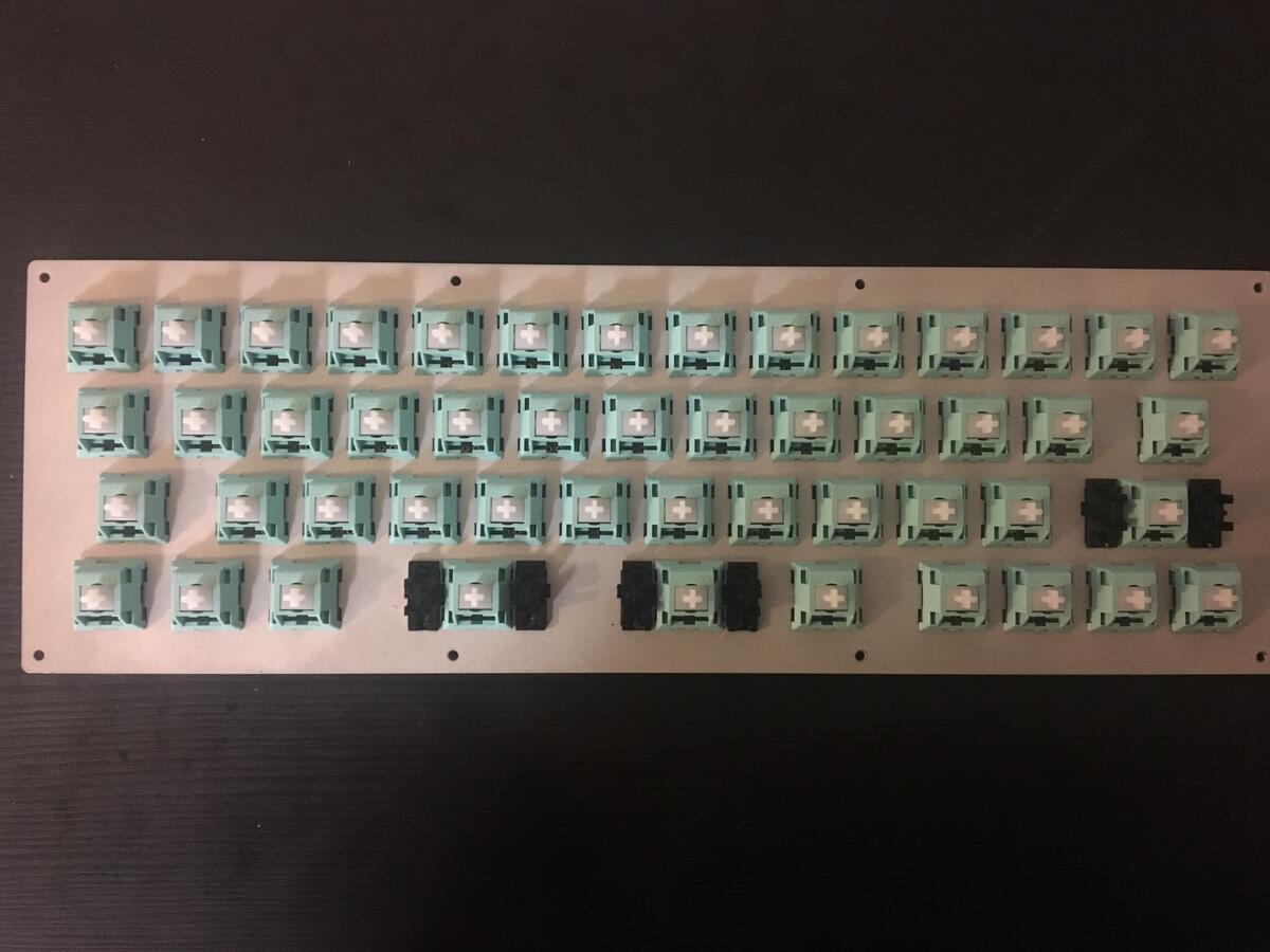
Switches & Amoebas
I used Outemu Sky switches because I’m partial to tactile, non-clicky switches. I’m not too picky on which kind; I think I’ve made every single board with a different kind of switch.
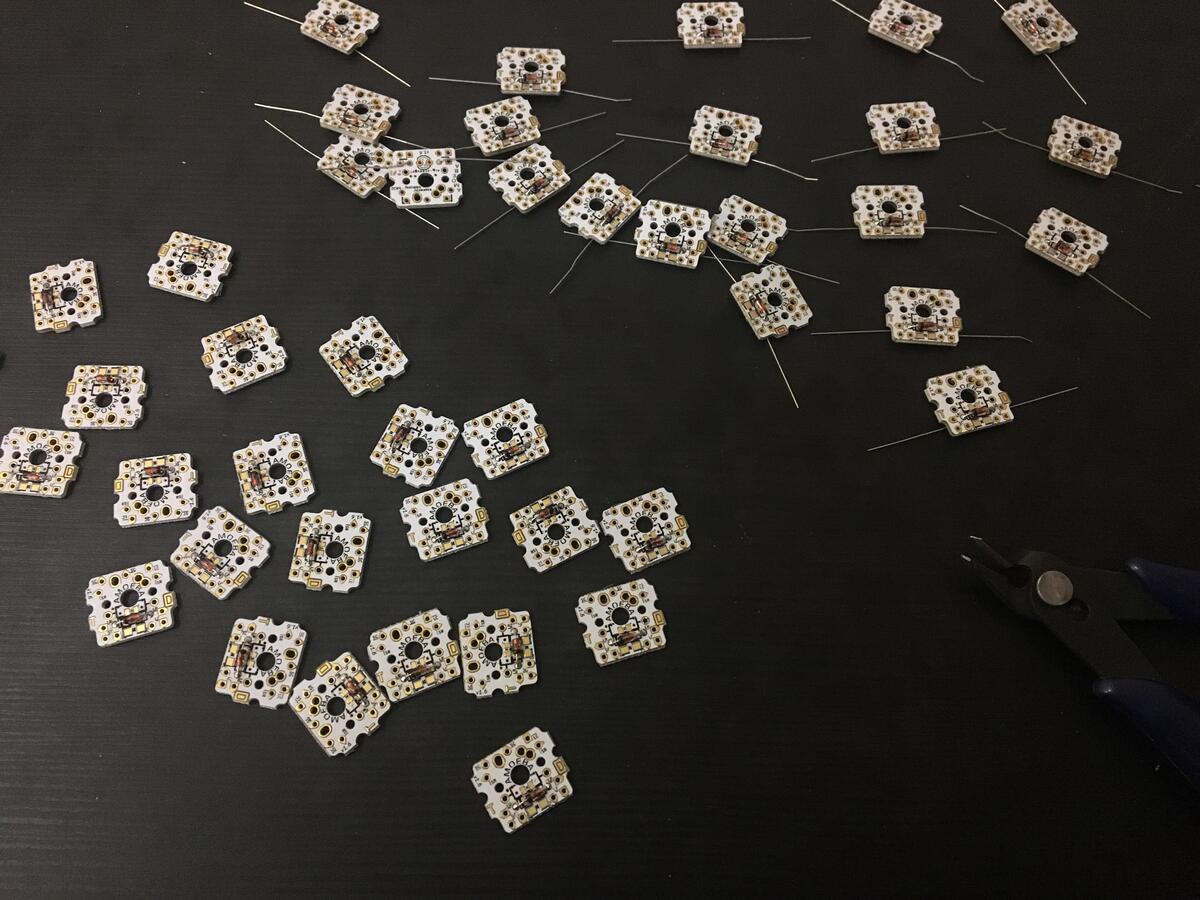
I also got a bunch of the 1-switch Amoeba PCBs, which are individual boards that make the wiring a little cleaner, since then I wouldn’t have to solder every wire to the switch legs individually.
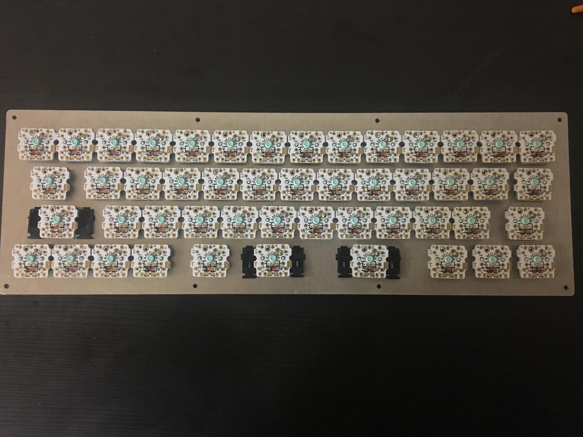
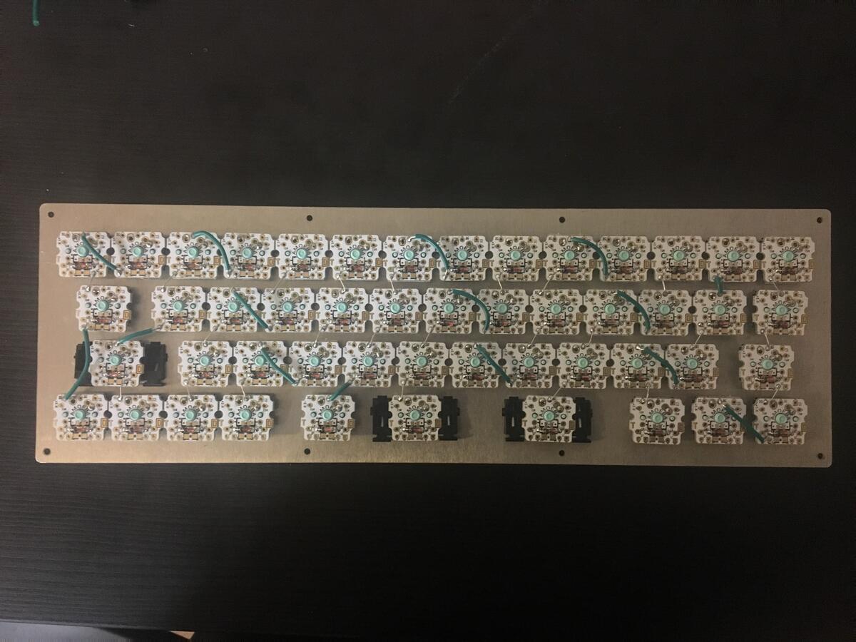
Some shots of putting together the switches and Amoebas:
Matrix Design
After setting down the switches, it was time to wire it all up!
Because a keyboard often has a lot more switches than there are pins in a microcontroller, QMK uses a matrix to wire up the keyboard. Instead of requiring a pin per key, it instead uses 1 pin for each row on the keyboard and 1 for each column.
Unfortunately, this is where I wish I planned ahead a little better. The design for this board would very naturally separate into a matrix of 4 rows, but unless I was willing to do some real ugly finagling, this would require 14 columns:
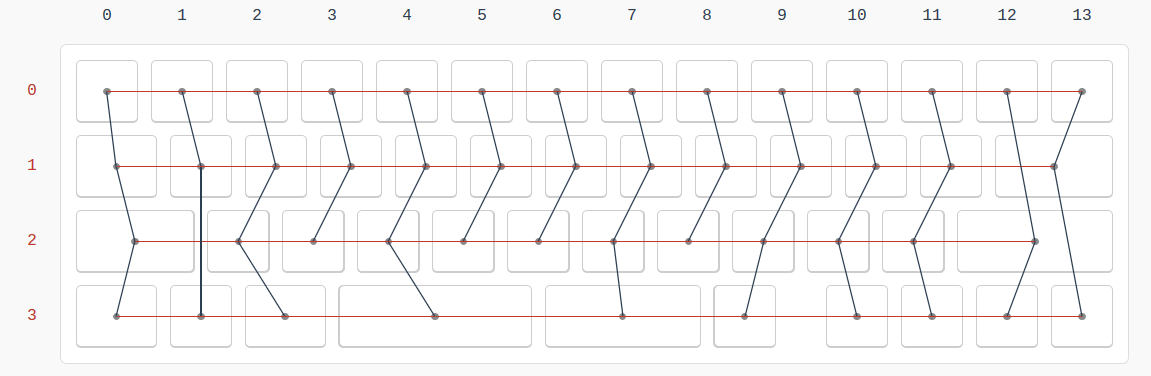
…which would require 18 pins. And the Feather module has 17 usable pins.
The board has 49 keys, so theoretically I could’ve made a 4 row / 13 column layout, but then the logical rows and columns wouldn’t match up at all with reality, which cluttered up the whole design. And if I was going to separate logical representation from reality in that way, I decided I might as well try to do it as efficiently as possible.
In the end, I decided on creating a 5 ‘row’ and 10 ‘column’ matrix, that looked like this:
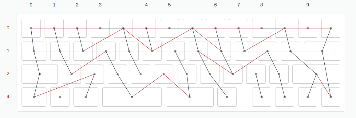
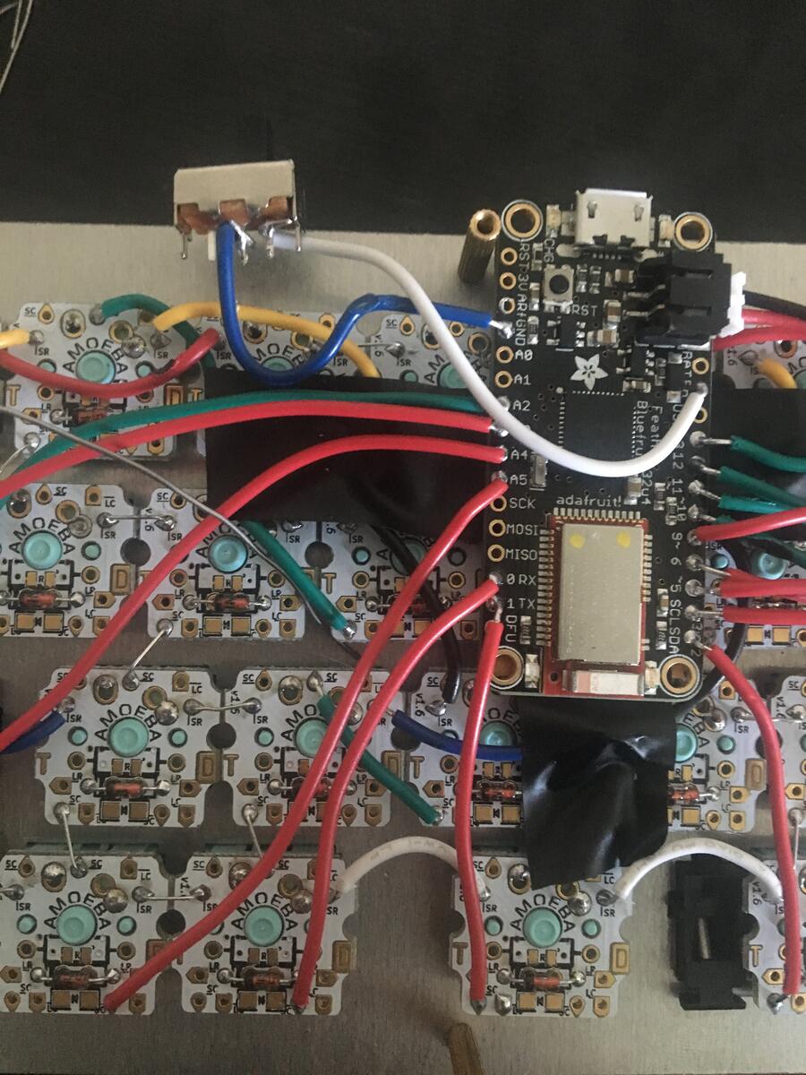
I thought about doing 6 / 8, but that had so many crossing over pieces that it looked overly difficult to build. 5 / 10 isn’t pretty, but it looked doable, so that’s the design I stuck with. On the actual board with the Amoebas, I planned out the wiring to look like:
Red wires are for the columns, and every color besides red is for a different row.
Firmware
I used kbfirmwarebuilder to create the firmware that would go onto this board. The main task here was making sure that the firmware matched how I would wire up the board, and that all the wires were soldered to the proper pins.
This was the pinout reference I used. Besides making sure to avoid the important pins (ground, voltage, etc.) I sort of arbitrarily used the pins by proximity, since we didn’t need any particular component to use an analog vs digital pin.
The only thing I did to test the firmware was to flash it onto the board, and then shorting out a row and column and seeing if it produced the correct keycode (simulating pressing the key on the keyboard).
Soldering the Matrix
All the thinking work was done, so now was just the labor of putting the whole thing together.
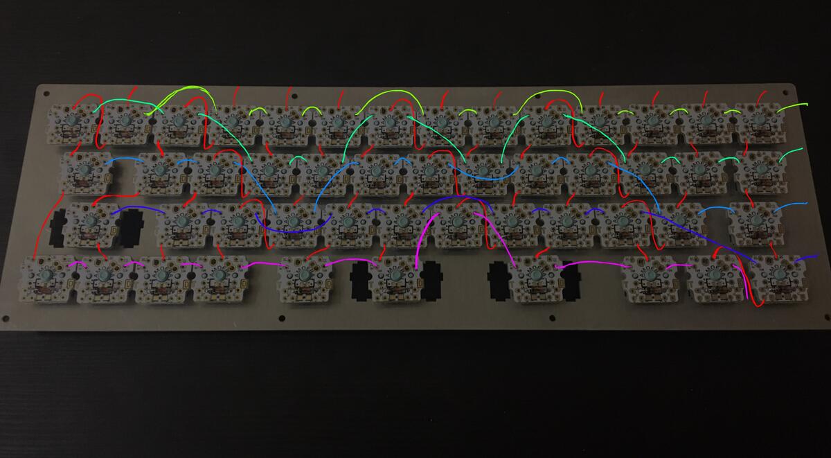
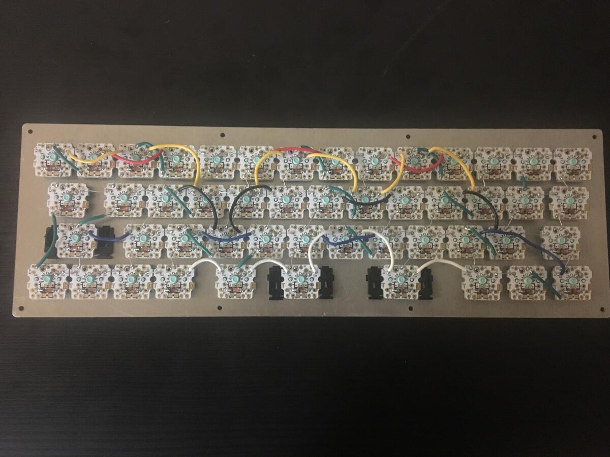
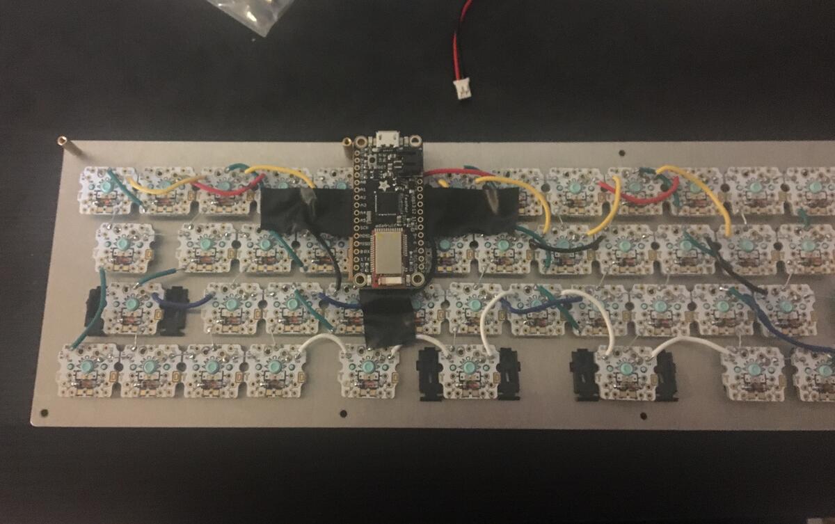
As it turns out, having a wackadoodle matrix makes for some ugly ugly wiring.
- Columns (green)
- Second row (first row: red, second row: yellow)
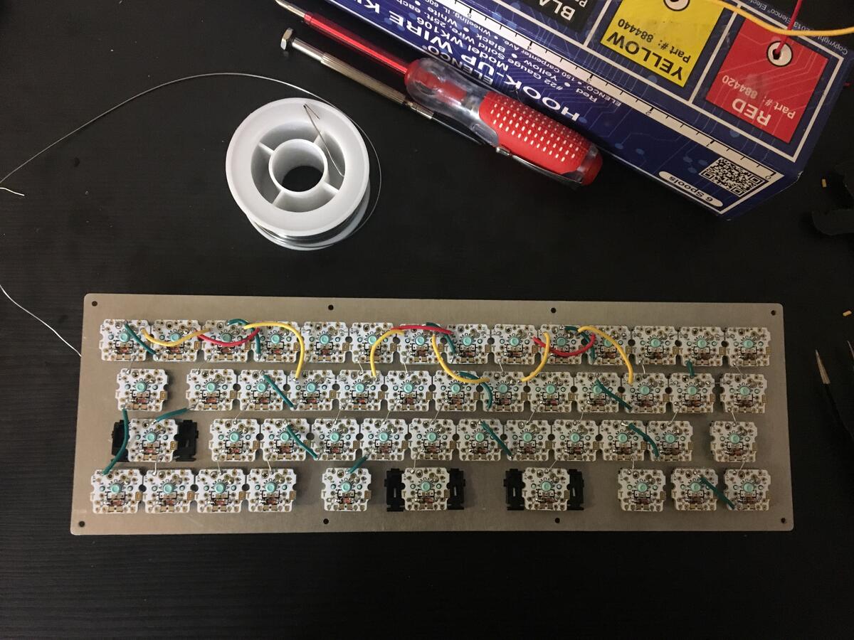
- Fourth row (third row: black, fourth row: blue)
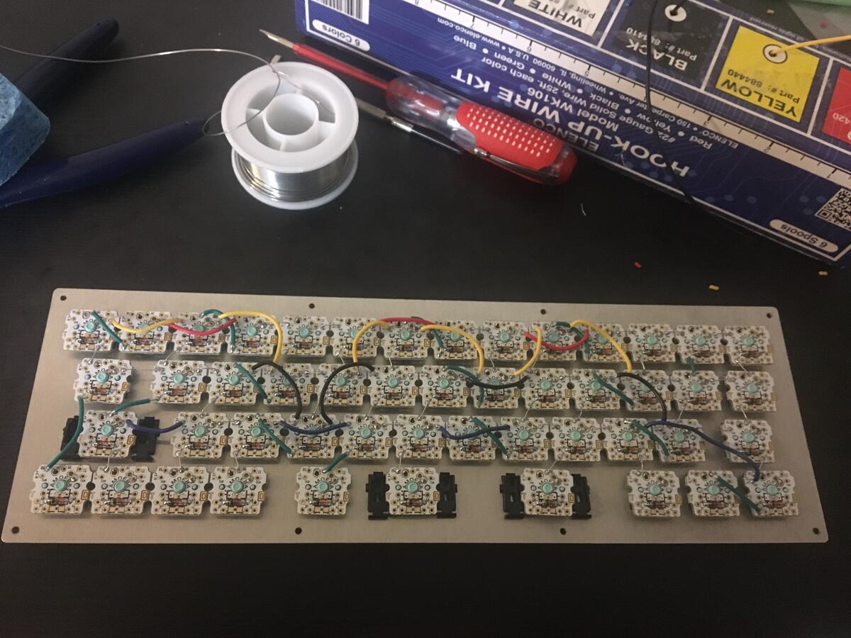
- Fifth row (white)
Soldering Bluetooth Feather
I didn’t want there to be any short-circuits from the Feather’s pins accidentally touching a switch or something. So I created a pretty hacked-together cardboard rest for the Feather, and taped it on the board:
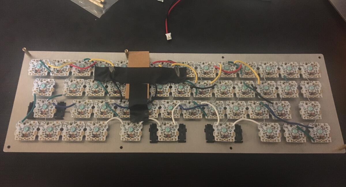
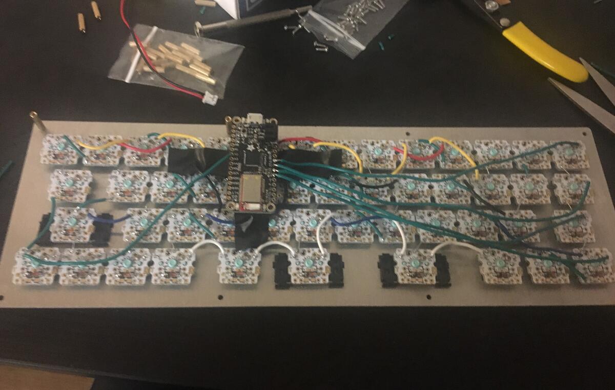
Then soldered the matrix to the Feather.
All rows soldered (green):
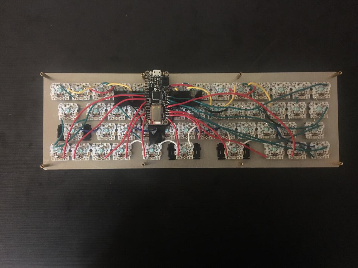
All columns soldered (red):
Power Button